- 2014-5-23
- CONSTRUCTION II / Bouts, III. CONSTRUCTION OF THE FINAL CELLO
- 5string, bouts, cello, construction
CONSTRUCTION II / Bouts
(Note: Until indicated otherwise the following construction-process will not differ from the construction-process of a four string cello. Please skip this part if you already know about the basic construction of a cello. Because we did not, and assumed that most cellists don’t either, we included those steps in this report.)
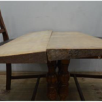
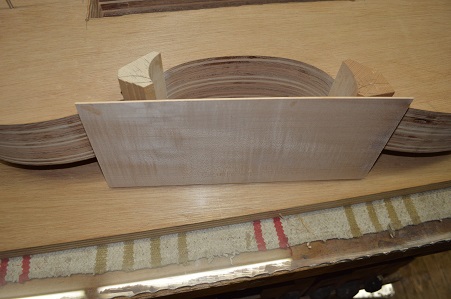
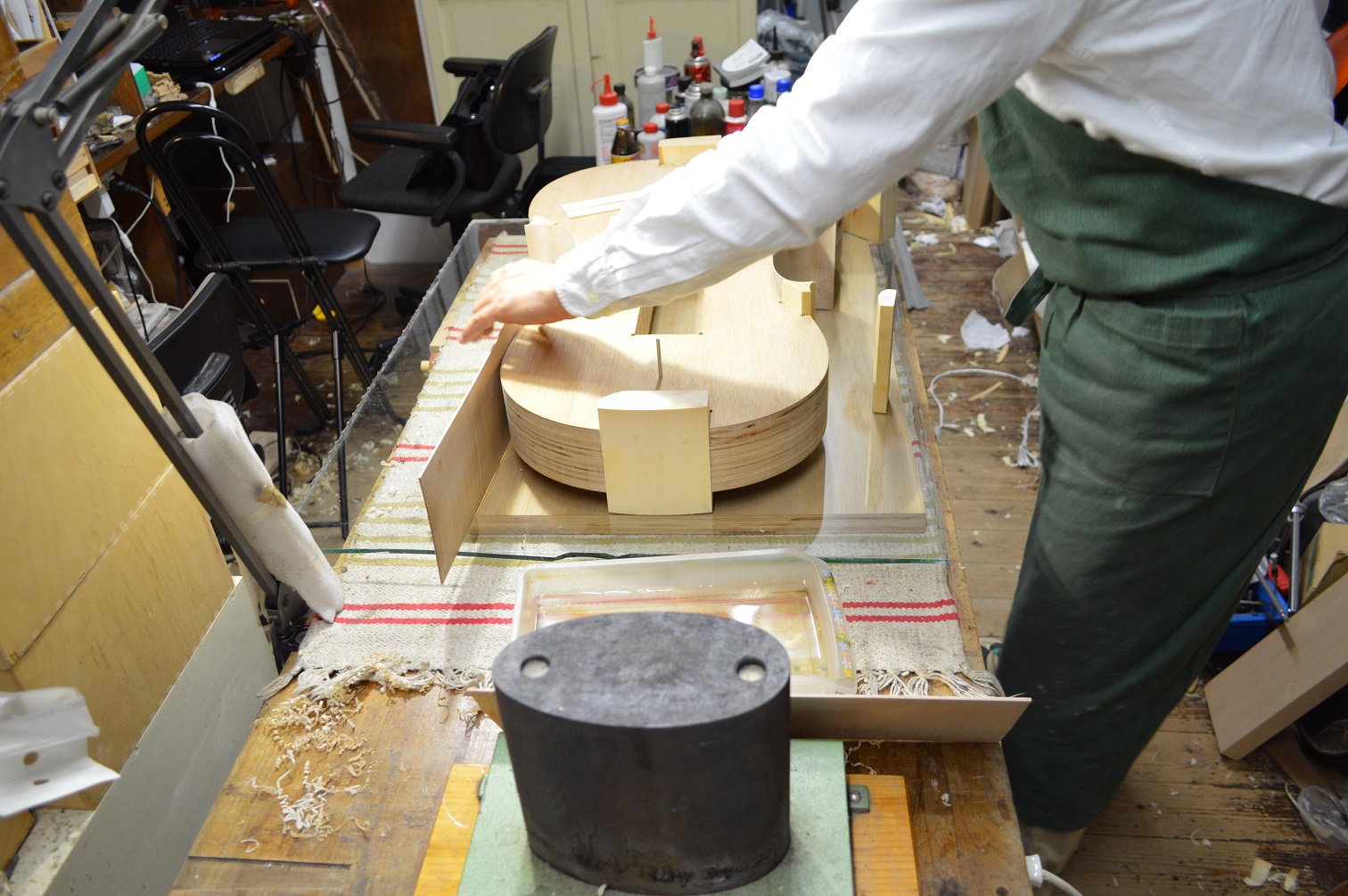
In the beginning of May 2014 Ueda started to work on the bouts of the new instrument. In order to assure the bouts fit in a perfect angle to the form he placed the form on a glass plate.
(Click on pictures to enlarge.)
Picture 32: The form on a glass plate. The blocks are now glued-on but will be removed later together with the completed bouts.

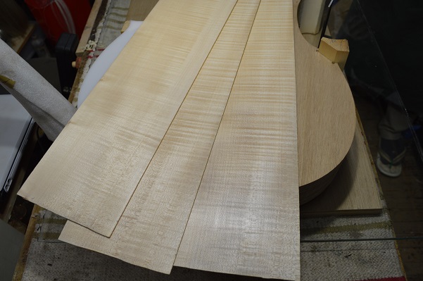
He then cut the wood intended to become the bouts into 6 separate stripes.
Picture 33: A selection of the bout stripes.
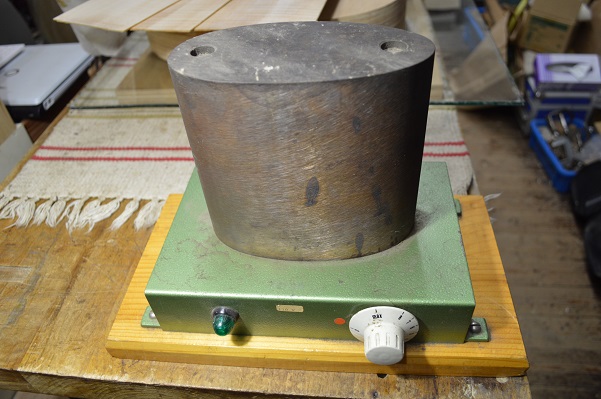
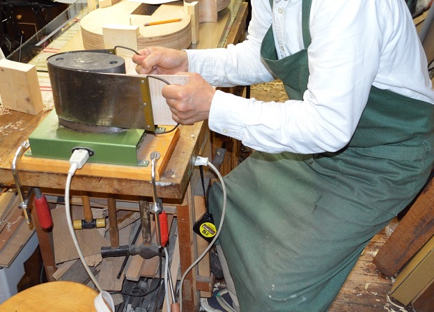
For the necessary bending of the bout stripes Ueda prepared to use a tool called bending iron. It is an oval block of iron that can be electrically heated to temperatures well over 100 degrees Celsius.
Picture 34: The bending iron.
The first bout stripe Ueda started with was one of the C-bouts.
Picture 35: AC-bout stripe before the bending process.
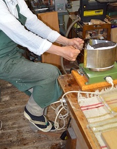
While heating up the iron he put the C-bout stripe for some minutes into a bowl of water. He then covered the moist stripe with a piece of paper which is supposed to increase the amount of steam that is necessary to bend the wood. Using a flexible metal plate he then started bending the bout on the hot iron, a process that requires quite a lot of physical force.
Picture 36 and 37: Bending a C-bout stripe.

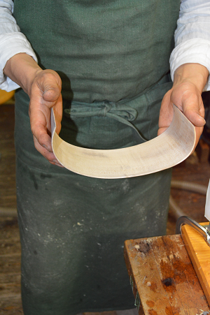
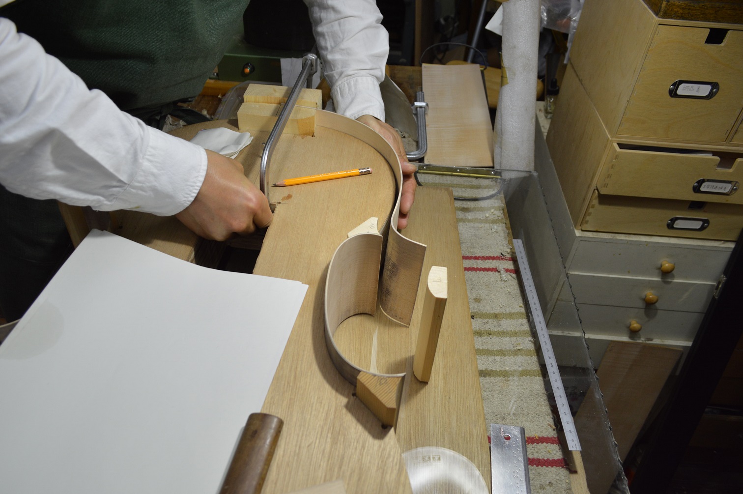
The bending process needs to be repeated frequently until the piece fits perfectly to the form. Picture 38 shows the first result and pictures 39 and 40 show the preparations for the first adjustments by marking irregular parts and whetting selected areas of the bout with water before bending it again.
Picture 38,39 and 40
Picture 41: Fitting the C-bout into place.
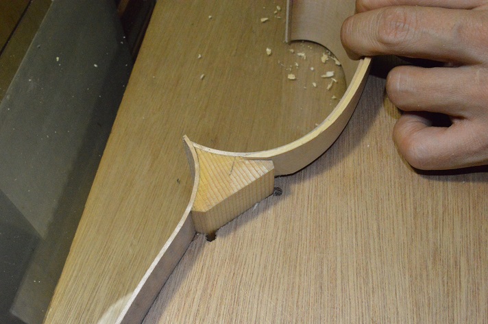
After Ueda had fit in the second C-bout he carved the corner blocks to their final shape.
Picture 42: Second C-bout and shaped blocks. (At this moment the C-bouts are already glued-on. Later pictures will illustrate the gluing procedure in greater detail.)
The next pictures show the process of bending and positioning one of the shoulder bouts.
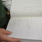
Picture 43: Measuring the length of the shoulder bout.
Picture 44: Bending of the shoulder bout.
Pictures 45 and 46: First fittings of the shoulder bout.
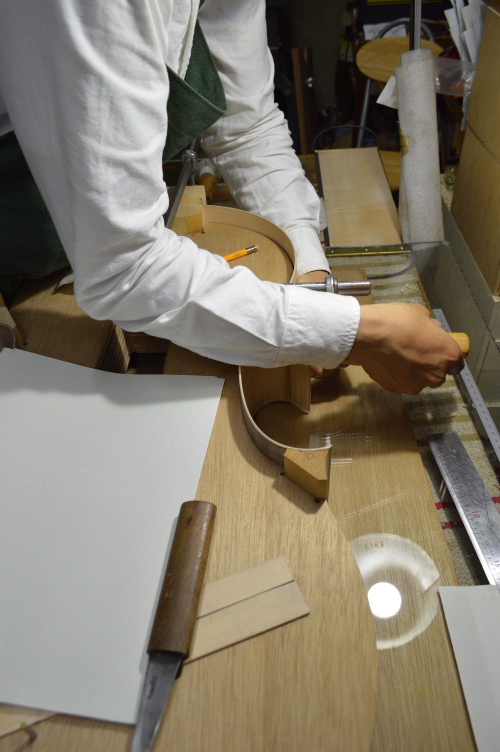
Picture 47: Positioning of the shoulder bout.
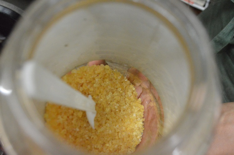
In the next procedure the upper bouts will be glued onto the neck- and the C-bout blocks. The glue master violin makers use is made from boiled animal hide, usually from cows’ or horses’ hides. Its cohesive power is much superior to the emulsions bonds’ used for cheap instruments or cheap furniture. It usually comes in granulated form, but also in stick shapes.
Picture 48: The glue in its unheated form.
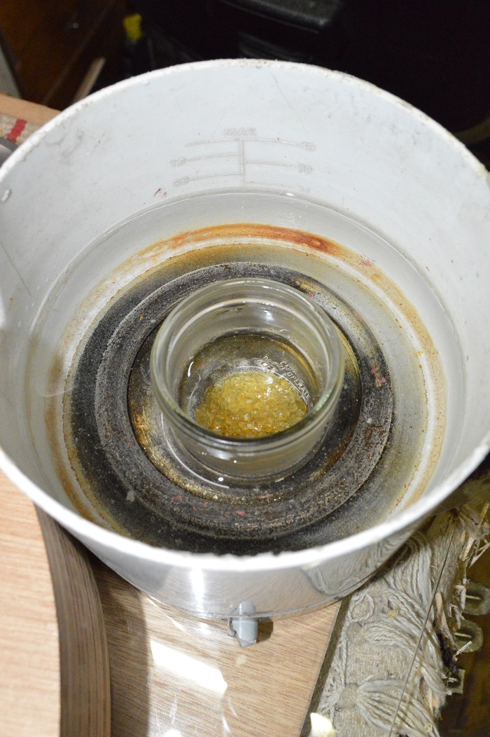
The glue then is slowly heated in water to 70-80 degrees Celsius which takes about 30 to 40 minutes. Bringing it to a boiling point would destroy its structure and make it useless. Master violin makers only heat up the amount they want to use in one session; if there is any leftover they prefer throwing it away over heating it up again at a later session.
Picture 49: The glue being heated.
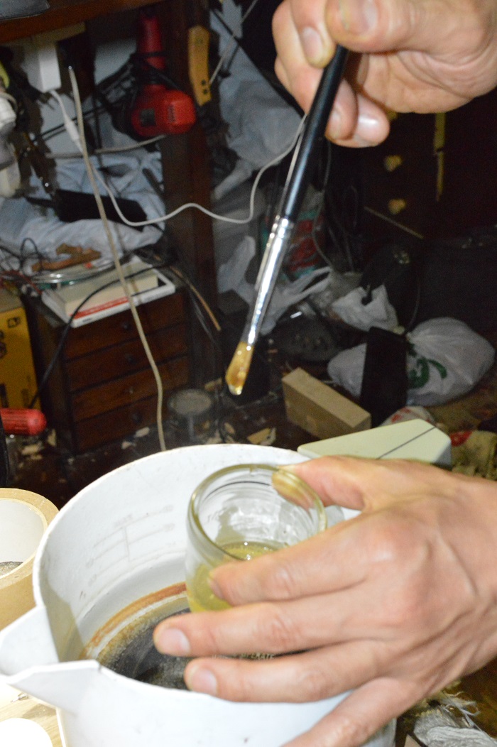
Picture 50: Testing the consistence of the glue.
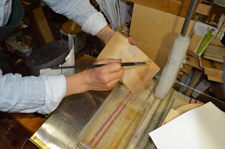
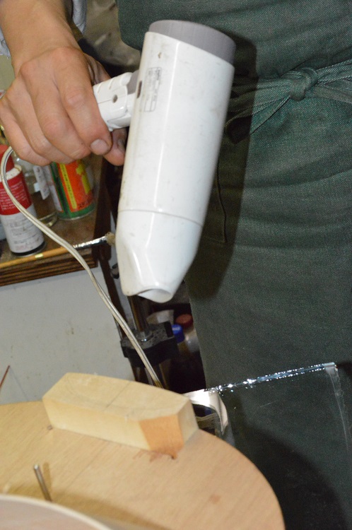
The relevant blocks then are scratched in several places to allow for deeper penetration of the glue into the wood. In order to avoid the bouts sticking to the form near the blocks because of possible spill-over of glue, soap is being applied near the blocks. The block then is pre-heated with a dryer to avoid a sudden cooling-down of the glue when coming in contact with the wood which would have a negative influence on its cohesive power.
Picture 51: Scratching of a block.
Picture 52: Soaping.

Picture 53: Pre-warming.
Picture 54: Applying glue to the neck bouts.
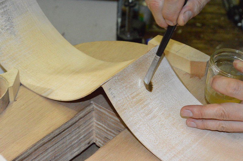
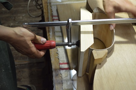
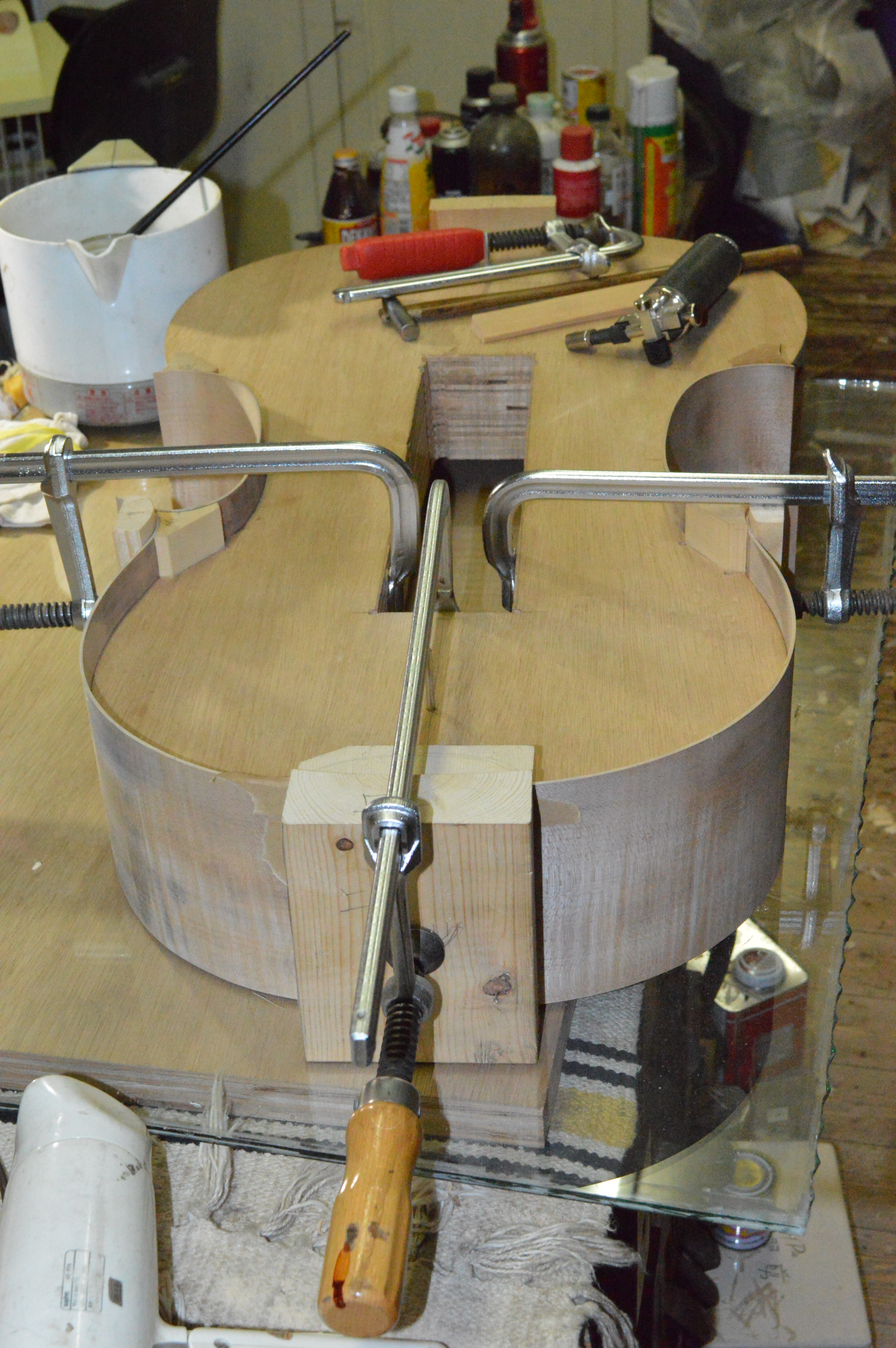
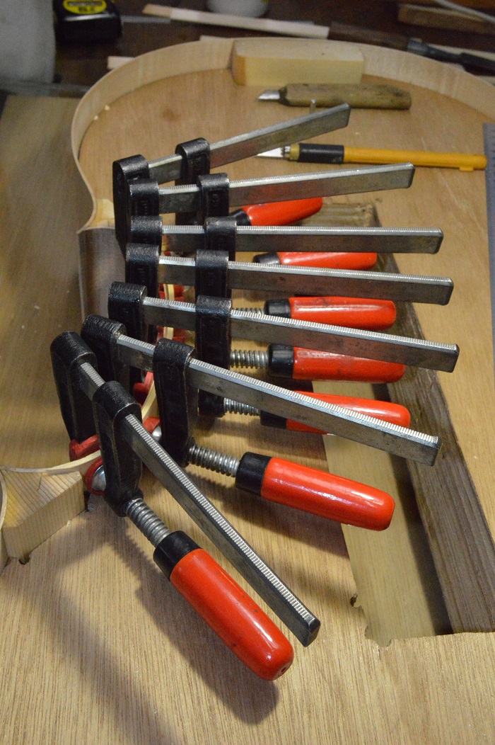
To avoid the pre-heated blocks to cool down the glue is applied very quickly and the bouts are fixed into place immediately.
Picture 55: Fixing bouts to the neck end.

Picture 56: Putting glue on at the C-bout.

.
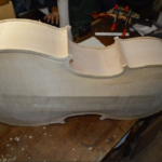
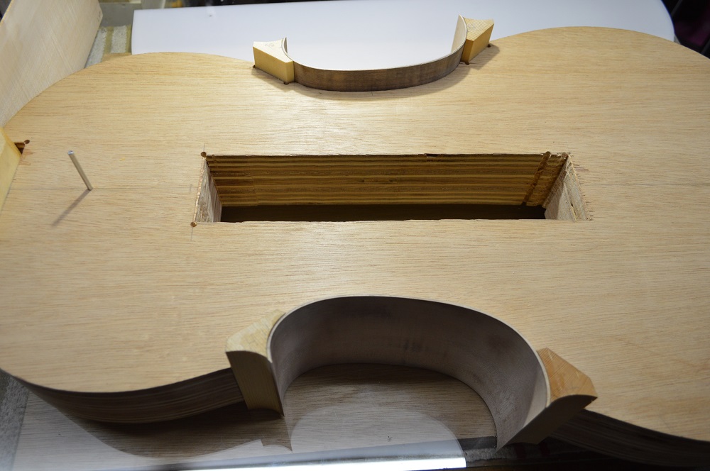
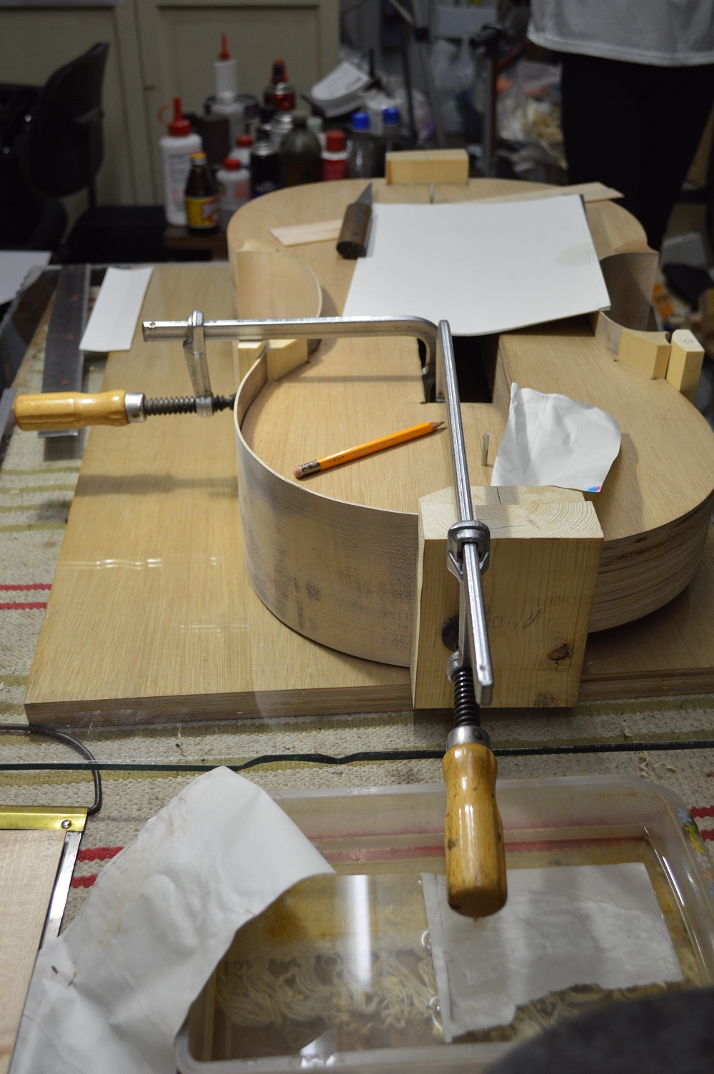
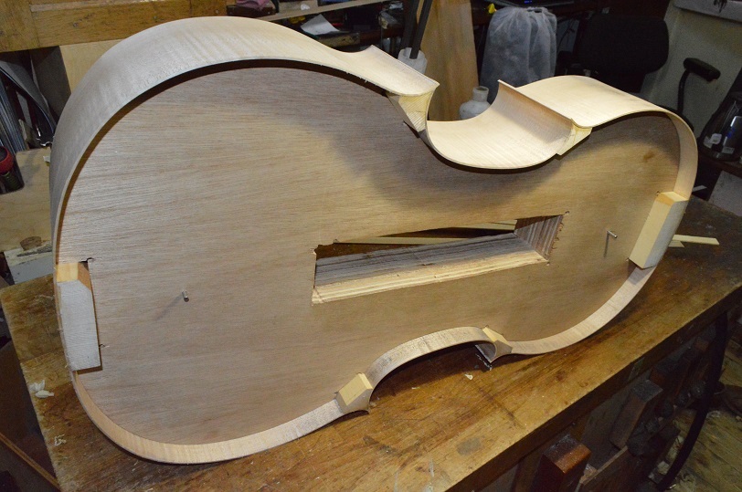
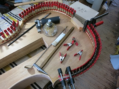
Picture 57: Both upper bouts are fixed into place.
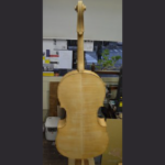
Pictures 58 and 59: Bouts are complete.
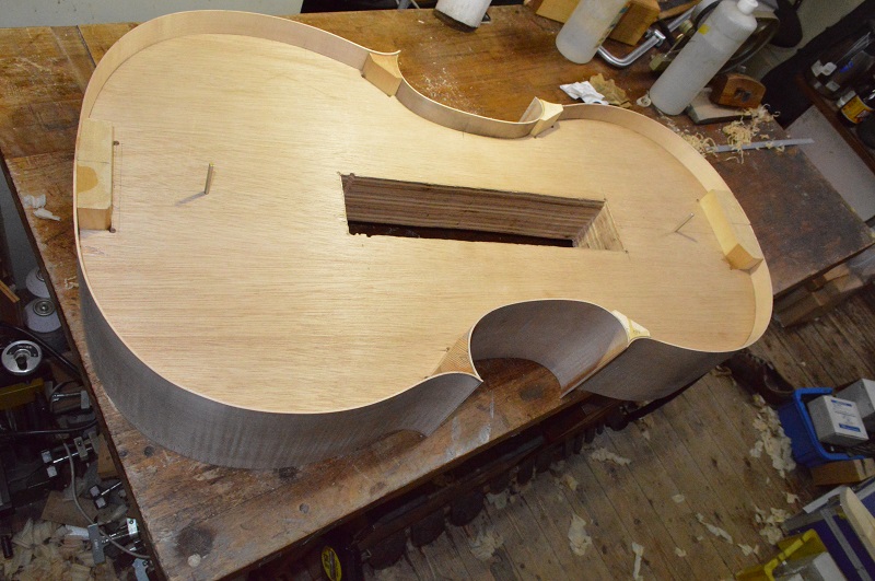
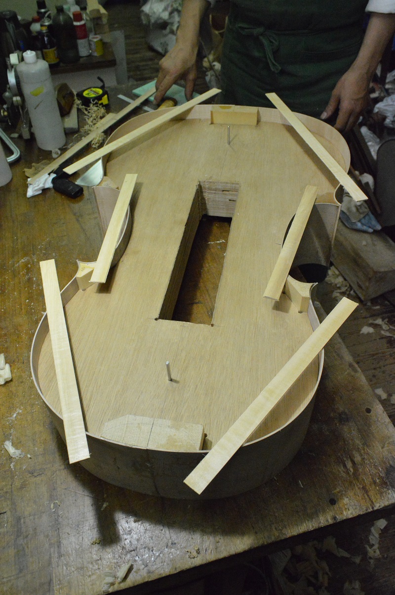
After completing the bout frame the linings were produced. Linings are used as a reinforcement of the bouts on the inner side of the frame.
Pictures 60 and 61: Preparation of the linings.

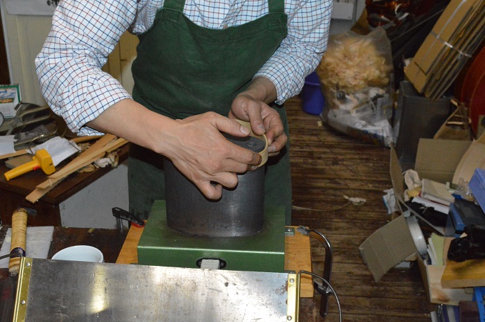
The six parts will be bent with the bending iron and then will be glued to the inner upper part of the bout frame. The inner lower part linings will be glued-in after the form has been removed. (There are also different approaches, for example the J.Kantuscher system, which uses a collapsible form that can be removed after all the linings are glued-in. In this project the traditional solid form will be used.)
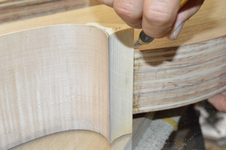
Picture 62: Bending a C-bout lining.
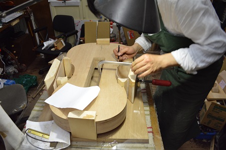
Picture 63: Opening a C-bout block before inserting the lining.
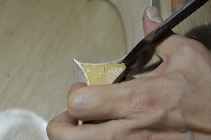
Picture 64: Fitting-in of the lining of a C-bout.
Picture 65: Provisional positioning of the lining of a C-bout.
Picture 66: Shoulder lining in position.
This basically finishes the construction of the bouts. The second lining will be added after the belly is glued-on and the form is removed.